3D Printing a Gearbox for a DC Motor
If you've dabbled in building simple electronic circuits, you've likely encountered a variety of motors. There are stepper motors that can obey your command to precisely perform a 1/3200th rotation, servo motors that can reliably move their arm 90 degrees back and forth on command, DC motors that can tirelessly spin their shaft at 1000s of RPMs, and more.
Each have their place, but there is a good chance that the first motor you encountered in your electronics/motor tinkering voyage, looked something like this 130 size DC hobby motor:
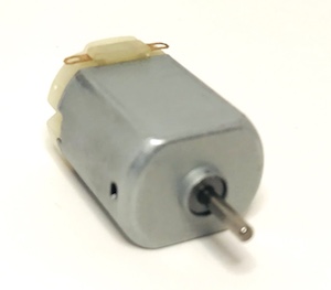
Why? Because they are incredibly low-cost (a pack of five should cost in the ballpark of $5-$10), they are easily powered by a couple of AAA or AA batteries in series, and in their most simplistic case they require zero external circuitry other than a connection to the power source. So, with this type of motor a wide variety of electromechanical projects are feasible with very few parts and very little cost. That's a great thing! In my family we've built dozens of 4M kits -- cable cars, dragsters, soda can robots, and more. Many of those projects have this type of motor at their core.
Experimenting with Size 130 Brushed DC Motors
However, if you are like me, when you fire up a typical Size 130 Brushed DC Motor for your own custom project, the RPMs (often in the ballpark of 10,000 RPMs), and the low torque (ballpark: 75oz-inch), limit the usefulness of these motors (at least without further PWM drivers or gearing). I remember grand visions of directly connecting wheels onto each of four Size 130s, rigging up some wooden or plastic framing to hold them together in a car shape, and firing up my "car" to rocket across the room. Alas, such a design is only feasable with an incredibly light body and even then, would probably need to be a substantially downhill terrain. Even then, RPM would be excessive, and torque in very short supply. Not a very feasible design.
You'd like to trade away some of those excess RPMs for some more torque, wouldn't you? I would.
Gearing Down, With Precision
One of the more intuitive ways (perhaps the most efficient way?) to increase torque while reducing the RPM of a brushed DC motor, is to use the motor in combination with a gearbox. DC motors with gearboxes pre-attached are readily available:
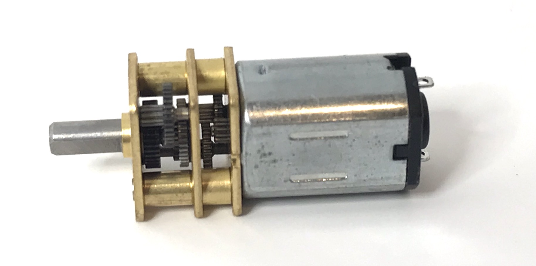
Clearly if you were building a commercial product or anything requiring durability, this is the route you'd go -- a metal gearbox manufactured to precise standards, with credible gear ratio specifications and output going to a D-Shaft spindle. It's not uncommon for the gearboxed version of a Size 130 motor to run for 3x - 5x the price of the bare motor, but the intricate machining involved (zoom in on the picture above) would seem to reasonably explain the cost.
Still, as a hobbyist, I find it much more interesting to teach myself the basics at a more primitive level first, before "buying my way out" of a challenge. Thus, the 3D Printed Gearbox was born. Here's how to build it...
3D Printing a Gearbox - Gathering Supplies
As a challenge to myself, I set out to create a 3D Printed gearbox with as few purchased parts as possible. I allowed myself only the following (in addition to my LulzBot Mini 3D Printer and PLA filament):
- Motor: one Size 130 Brushed DC motor. Can't get by without that!
- Power: one battery pack connecting two AAA batteries in series.
- Shaft: one approximately 4 inch long 2mm shaft, to use as an axle. Can't do much gearbox work without having one or more shafts for the gears to rotate on!
- Bolts/Nuts: two pair of 1/2" #8 machine screws and respective hex nuts. I think I could come up with a design that doesn't require any bolts or nuts, but we'll save that for another time.
- Alligator Clips: for convenience (although technically just a shortcut to postpone soldering), a pair of alligator clip test leads.
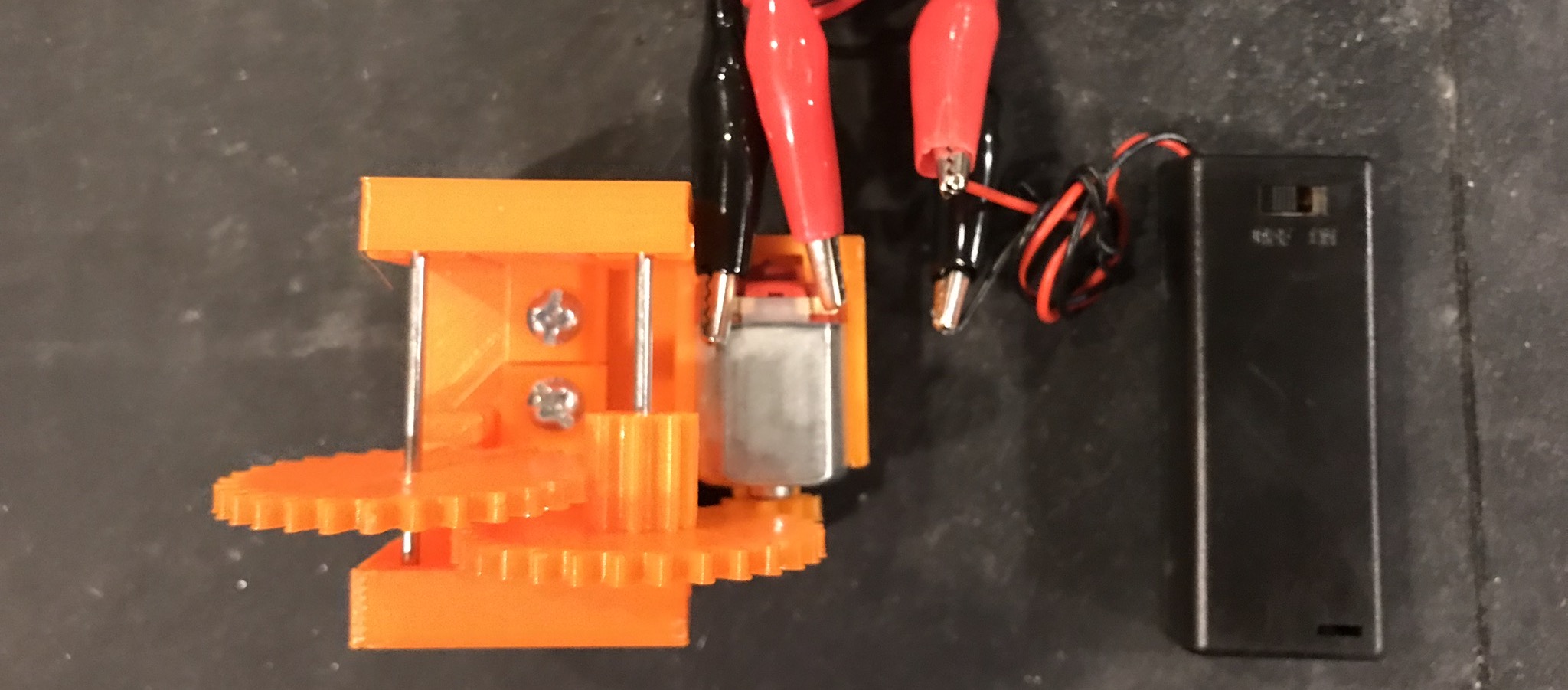
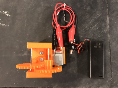
I think that's a pretty bare minimum of supplies:

...and, it's enough to build a 3D printed gearbox!
Printing the Gears, Gearbox, and Motor Mount
Here's an inventory of the 3D printed parts that go into the making of this gearbox, with intuitive (but perhaps not technically perfect) part names for reference:
| Component | Rendering | STL File Download |
| Motor Mount Assembly | 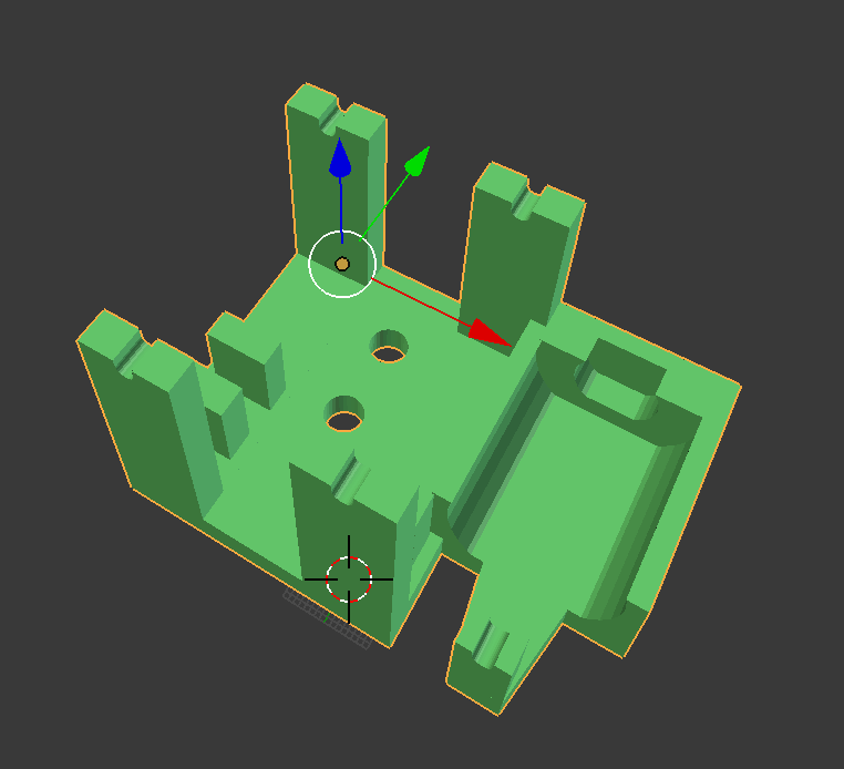 | Download STL |
| T Endcaps with 2 Footing Variations | 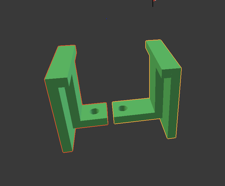 | (both required) |
| Compound Large/Small Gear |  | Download STL |
| Small Gear |  | Download STL |
| Large Gear | 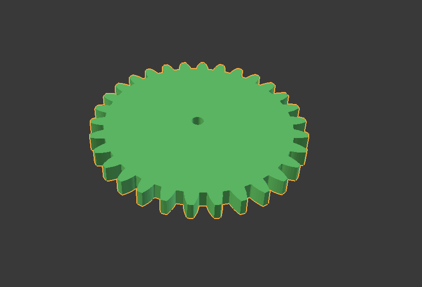 | Download STL |
Download all of the above STLs and print out (these STLs assume millimeter units). I used a LulzBot Mini with PolyLite PLA, which worked great for me.
Time to Assemble
Now that you've gathered all necessary hardware components and created 3D prints of all of the necessary STLs, the assembly steps are straightforward.
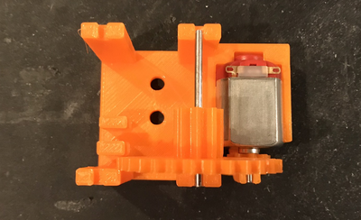
Step 1: Attach Motor to Motor Mount Assembly
Start by pressing the small gear onto the motor shaft. It will (and needs to be) a tight fit. You might need to press the small gear onto the motor shaft firmly by hand, and then turn the motor shaft-down onto a sacrificial board, and tap the back end of the motor with a hammer to get the small gear onto the shaft. Push the small gear onto the shaft as far as you can get it without creating friction against the motor body.
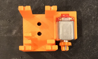
Then, snap the motor (with the small gear already on it), into the motor mount assembly. The fit of the motor in the mount should be very snug -- there shouldn't be any wiggle room. The shaft, though, should be easy to rotate by hand, demonstrating that when the project is powered, the spindle will be able to rotate free of any friction.

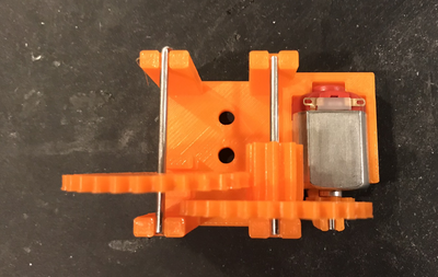
Step 2: Insert Compound Gear
Trim two pieces of 2mm shaft to perfectly fit the shaft groves in the motor mount assembly. One of the shaft pieces is needed for this step, the other for an upcoming step. The two pieces of 2mm shaft should be approximately 40mm long, each. An easy/simple way to trim shafts, is with the screw shear portion of a typical wire stripper.
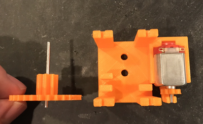
Slide the compound gear onto one of the shaft pieces, with the large gear portion of the compound gear nearly at the end of the shaft, but pushing just enough additional shaft length through the gear to allow the shaft to sit within the shaft grove pair that is closest to the motor.

Step 3: Insert Large Gear
Using the remaining 2mm shaft piece (of approximately 40mm length), slide on the large gear, dock the shaft in the shaft groves furthest from the motor, and adjust the large gear position on the shaft so that it mates with the small portion of the compound gear.
The motor mount assembly has guides (not visible in picture) that indicate precisely where the large motor should be positioned. Between the guides on the motor mount assembly, should be just enough room for the large gear to spin without friction on the guides.
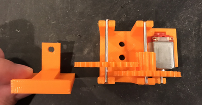
Step 4: Secure the Geared End of the Shafts
Notice that in the prior step, the shafts were merely "resting" in the shaft groves. In this step and the next, we'll secure the shafts to prevent them from making any motion other than rotational.
Of the two T Endcaps, locate the one with the longer footing. Slide the T Endcap into place, such that it's footing hole aligns with the corresponding hole on the motor mount assembly.
By positioning the T Endcap in this manner, the ends of the shafts closest to the gears, will now be secured on all sides.


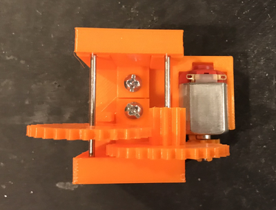
Step 5: Secure the Remaining End of the Shafts
Slide the remaining T Endcap into place, such that it's footing hole aligns with the corresponding hole on the motor mount assembly.
At this point, both ends of both shafts should be fully enclosed, restricted from any non-rotational motion.


Step 6: Bolt the T Endcaps to the Assembly
Using the #8 1/2" machined screws, bolt the T Endcaps to the Motor Mount Assembly.
Step 7: Attach the Power Source
Using the alligator clip cables (or, if you prefer, by soldering), attach the battery holder leads to the motor tabs.
Then, insert batteries into the battery holder.
Step 8: Mark the Gears
To make it easier to observe the "gearing down" mechanics of the gearbox, mark the gears with some visible tape or marker.
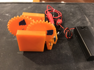
You should now be able to turn on the power switch on the battery holder, and watch the gearbox in action, successfully "gearing down":
If you watch the above video closely, you'll be able to observe that the leftmost motor is rotating substantially slower (10x slower, in fact) than the middle (compound gear). Furthermore, although it is difficult to observe in the video, the compound gear is rotating 10x slower than the small gear attached to the motor shaft. So, our 3D printed gearbox is successfully "gearing down" this motor by a factor of 100x! Success!
Conclusion & Possible Improvements
Although this form of 3D printed gearbox is no match for the durability of a commercially produced gearbox, I found it to be an excellent lesson in the mechanics of gearbox creation, as well as an interesting challenge in building a gearbox with minimal supplies. I'm glad to have #justbuiltit -- hope you'll give it a try too!
In a future refinement, I might consider reducing the reliance on purchased parts further -- I believe that with some refinements to the motor mount assembly, it might be possible to eliminate the need for the metal shafts, the bolts, and the nuts.
Until next time!